|
|
index
555 touch sensor
air mike
amplify your toy
box your toy
circuit sniffing
clock tickling
contact mike
electret mike
hack the clock
laying and hacking
laying of hands
light theremin
make a cable
mapping
pickup
piezo driver
resistors
soldering
sudomini
synthesis
tape head
|
Make your own capacitative touch sensor, (based on Forest Mimms' design).
You will need:
- 555 timer chip
- LED or circuit
- 10K-100K resistor
- 1/2.2/4.7/10uF capacitor (I find 1uF capacitors work best, but feel free to try others)
- 0.01uF capacitor
- battery/power supply
- NB you'll need to ensure you're grounded for this circuit to operate correctly (touch something connected to the ground).

- It may help to have a second antenna plugged into the ground rail.

- Experiment with various sizes of the larger electrolytic capacitor and see the effects of your changes

- Similarly, experiment with different resisitor values.

- You may find that 9v is too much, use your arduino as a power supply instead.

See my use of this technology here:

- Triggered (King's Place, London, June 2011): 3 - Metapiano excerpts 1m 30s
- Triggered (King's Place, London, June 13th 2011): 2 - Glyphs
- Triggered (King's Place, London, June 2011): 1 - Gaggle/Wired

Also try plugging directly into a speaker (but not headphones)
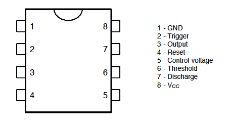
Layout of 555 chip:
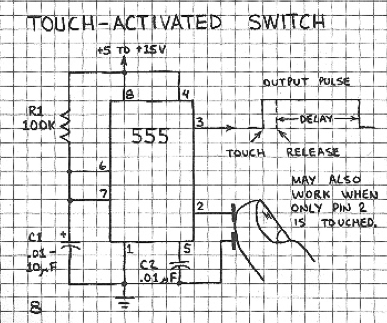
Forrest Mimm's schematic:
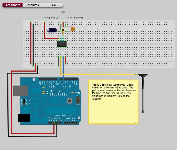
Fritzing plan:
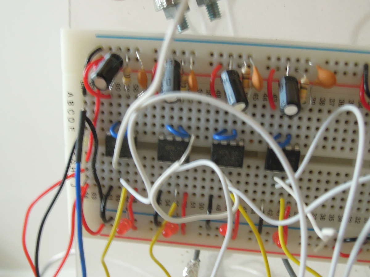
- (Rather blurry) photo: http://rhoadley.net/images/cbhh/555_touch.JPG

- Turn on an LED or circuit by touch alone.

- Make the circuit above, test with LED and then insert into another task as a switch, for instance.

- Try this other design for a touch sensor...
 The Task The Task
- Make the circuit above, test with LED and then insert into another task as a switch, for instance.
- Experiment with different resistors, capacitors and ways of interaction and output and fully document these.
- Document the process with plans, photos and, yes, videos of it and of it working!
- Media files
You must submit media files, such as video, audio or image files, but please ensure that video files are compressed to a reasonable degree. You should never submit dv files, but compress these to mp4. You should submit no file that is greater in size than 25MB/minute.
- Added value
By completing the details of the task you will achieve at least a pass mark. By imaginatively and creatively considering how you might implement the task originally you can add value to your submission, and this added value may increase your mark significantly. Even when making videos of short demonstration tasks try to consider musical and performance criteria.
- Suggested questions to consider answering in your logbook
- You may find that this circuit is particularly sensitive to voltage and capacitance. After experimentation did you find the to be true? Explain your findings.
- Include all these components in one section of your logbook. Include images within the logbook, and any audio or video recordings alongside.
- Submit your logbook to the i-Centre by 2pm on Tuesday 8th May 2018
|
|